


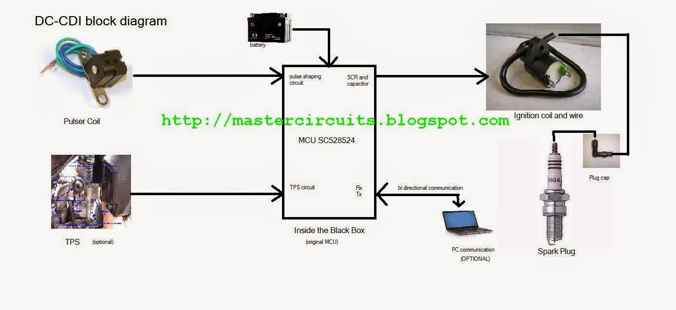
Looking at the picture (click to zoom), The MCU is actually made by freescale inc. a Motorola based MCU with a part number SC528524. The IC is actually a predefined package for the motorcycle manufacturer design, so getting the data out of it will be impossible, not unless you are one of the engineer and designer who actually built the black box.
The SC528524 is the heart of this CDI, it holds the data for generating the ignition map, the timing, the RPM limiter, the TPS switcher, the SCR gate trigger and the control of the High Voltage Converter. If and If only we have the datasheet of the MCU, perhaps we can be able to use the Rx and Tx pins to communicate it with a computer and proper software. But again, since it is a predefined MCU made only for them, reverse engineering with the current MCU is difficult.
 |
| Shogun DC-CDI MCU removed |
By tracing each section of the entire block box and redraw the schematic, all possible component of a good working ignition are all there, so by using any other MCU, an open source software may do the trick. How about using PIC Microcontroller made by Microchip, Yes there are lots of them all over the internet, just search them.
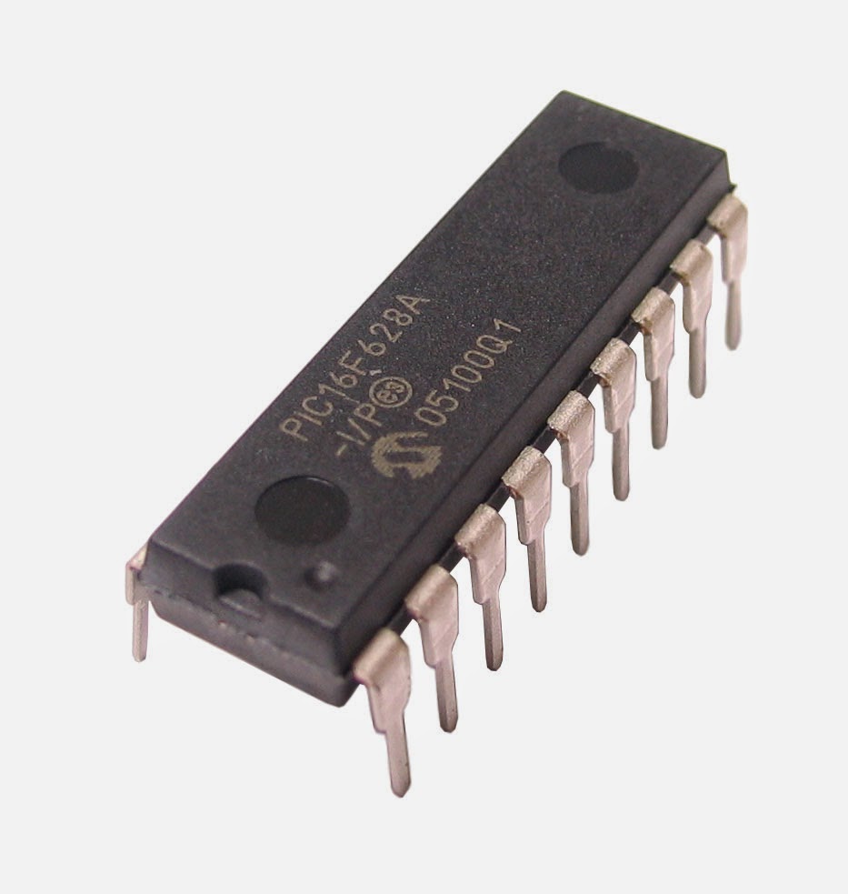 |
| pic16f628A by microchip |
Photo shown is a very popular ignition made for remote controlled planes, It is an open source project by many people in a forum. Hardware and Firmware for the 16f628A microchip are all posted here...
1. www.transmic.net
2. www.electronics.gompy.net/
Digital DC-CDI schematic (full schematic diagram of shogun 125cc ignition controller)
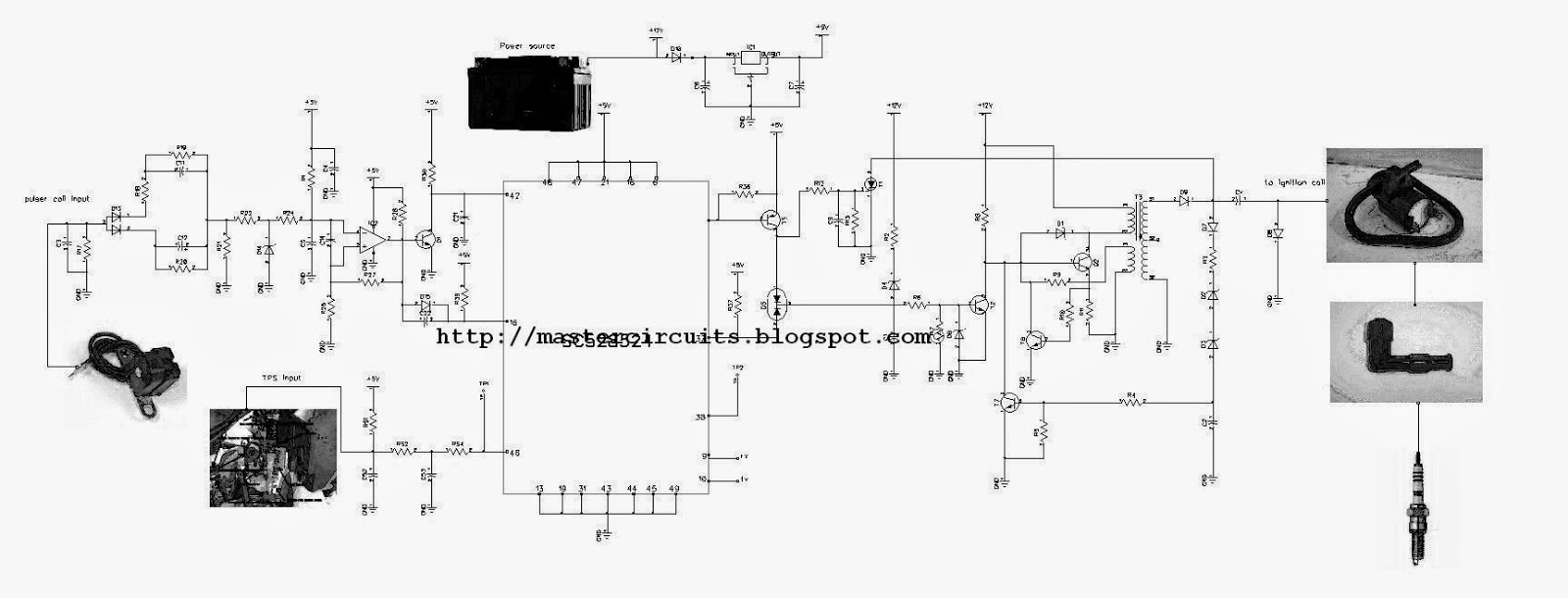 |
| Full schematic diagram of Suzuki Shogun DC-CDI |
1. Pulse Shaping Block
2. TPS Block
3. MCU block (heart of any digital CDI)
4. SCR/Capacitor block
5. High Voltage converter block (no alternator needed)
Pulse shaping and conditioner block
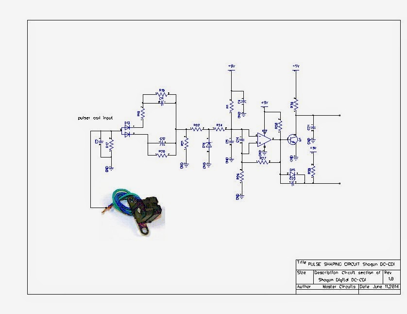
The circuit inside this block is responsible for the shaping and and clipping for the amplitude for the MCU to receive and access as the flywheel equipped with magnet passes through the pulser coil. Depending on the polarity of the coil, this circuit will receive that pulse every revolution whether positive or negative pulse. If the program of the MCU needs to receive only the negative pulse then this circuit will be responsible for making it a negative pulse if the polarity of the pulser is a positive output, and vice versa.
TPS block circuit

As the name implies. TPS corresponds to Throttle Positioning Sensor. This sense the throttle position by way of a switch fitted on the carburetor mainly, for improve acceleration purposes and or fuel efficiency delivery of the whole ignition front end. Not all CDI is equipped with such for a cdi can work with or without the TPS. But for an EFI system, TPS is a must. (but it will not covered with this article for the CDI being modified here is mainly for carbureted type ignition)
MCU block
The heart and source of all sensor and outputs the necessary command to the SCR, HV generator oscillator, and TPS input, as well as the pulser coil input. Depending on the firmware itself will make every cdi differs in performance and output. The stored ignition mapping will also tell the difference where the bike will pull hard at an RPM band. All CDI are created equal, only the ignition map differs. So why in the heck did they make such racing CDI if they are almost equal with the standard CDI. Theoretically, only the power on the certain RPM band will be moved, it will not grant you extra HP for a normal engine. If the engineers were able to get 50 reliable HP, they would have done it... but you can modify the distribution of the power. (Ex: more advance = more torque at a particular powerband) or remove the rev limiter that limits the probability of having above optimum performance.Concretely, to tune the advance curve according to the engine/exhaust/carburation/air filter and to get same extra HP, a real dynamometer will serve you as the basis of engine tuning, and not on the CDI alone.
SCR/Capacitor block

This is the area on when to charge and then discharge the capacitor the dump to the ignition coil. As the capacitor is charge by the HV converter, when the MCU sense the first pulse, it will then calculate everything via the ignition map stored on the MCU, either advance or retard, then trigger the scr gate at the right time..The engine will lose power when the CDI block fired the spark plug at the wrong timing due to wrong calculation and data of the MCU. so all in all, this block still rely on the MCU data.
High Voltage Converter Block
An important block for an ignition to be called DC-CDI. The circuit that is responsible of producing a large amount of voltage from 20kv up to 40kv, but of course depending on the design and topology used in this converter, the efficiency and reliability is important. Instead of having an external High voltage generator located in the generator side to which an AC-CDI use, DC-CDI do not have that kind of winding, instead it is placed inside the black box. An ocillator that is connected to the MCU SCR trigger output is needed to off and on the HV converter for charging and discharging the Capacitor and in sync with the SCR gate triggering to avoid the gate locking down during discharge. There are many design employed on a HV converter of dc-cdi, such as flyback converter, push pull converter, and the cheap low cost forward converter. In the circuitry above, they used the forward converter, only few components needed to have a cheap but reliable kind of converter for the CDI, although the efficiency is not that high in comparison with the flyback topology converter,
To be continued..for the placing of the pic16f628A and preliminary testing on the workbench before trying it on the bike,and communication with PC to update and change ignition map...Please be back thank you.

Really informative article! I am glad that you described the entire functioning in this blog. I need some help in buying a good generator for my home. In my opinion honda generator eu3000is is a good product to invest in. What do you think?
ReplyDeleteIm really glad to find you in inrernet .ive just finish repairing my cdi..by the help of youre very usefull blog..btw can you tell me where is the dumping diode that youve been telling in this blog..tnx preparing to test my cdi in my 7yrs old shogunr125 tnx alot
ReplyDeleteExcellent,im very glad to have found this blog, without your help i wouldnt be able to repair my motorcycle!!!!
ReplyDeleteAno na po ang update dito sir
ReplyDeleteIs it possible to convert my ac cdi with a dc cdi because the coil of high voltage that feeds ac dci often burns and my bike does not have spark...
ReplyDeleteYes you can as long as the correct ignition timing of the DC-CDI is the same as what you are using on your AC-CDI. For example if your motorcycle timing is 10 degree BTDC then u need the same specs of DC-CDI thus eliminating the use of HV generator coil.
ReplyDelete